Page 3

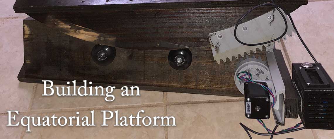
Building an Equatorial Platform
By Joel Carmona
Introduction
I've always had interest in astronomy growing up. Since joining the Brazos Valley Astronomy Club (BVAC), I have focused on learning how to find distant sky objects (DSOs) as well as planets. After attending a club star party and experiencing the different types of telescopes club member had, I decided a 12" Dobsonian telescope would satisfy me best.
I have a 12" Dobsonian telescope to observe the night sky. Learning to find DSOs can be difficult when done by oneself. I notice a major increase in objects I'm able to find when participating in BVAC group observations at a star party or after club meetings. After practicing many hours of finding DSOs, I gained experience in noticing how objects move out of the eyepiece field of view (FOV) because of earth's rotation. Before choosing the Dobsonian telescope, I really favored the go-to concept. But after experiencing different types of telescopes at a BVAC star party, my mind was completely changed to choose a Dobsonian, although I didn't like how it had no tracking features. So I set out to change this by thinking to mount motors and use a micro controller to track night sky objects. At first I wanted to mount two motors to track azimuth and altitude angles. But BVAC President, Tim Cowden, explained that even if I got the two-motor concept to work, I would need a third motor rotating the eyepiece to compensate for image rotation. Tim suggested I look into a equatorial platform to track and said that other amateur astronomers have built their own. So I went off and googled “equatorial platform” and was convinced to take this approach. It seemed more elegant to me, as a first step, to build a platform to track night sky objects.
I did have to make a design change after the platform was assembled. See photos 6, 7, 8, and 9 in the Project Pictures section below. I realized the sin(θ) term was introduced when driving the platform using an acme screw rod. This sin(θ) is introduced to the equation because of mapping from linear motion to angular motion. I was warned by Tim about this but decided to proceed to see how it showed itself. Essentially, if I hadn't made the change, the programming would have been more complex. I rather aim for simplicity, so I decided to design and 3d print a gear that would directly couple to the platform to eliminate the sin(θ) term in the rotational velocity equation of earth (i.e. 1 rotation / 24 hours). The gear is a planetary gear to spur gear coupling. Sixty (60) turns on the input of the gear is 1 turn on the output of the gear. This gear, along with the motor drive, will match the earth's rotational speed to keep an object steady in telescope eyepiece. The hope is to eventually take pictures of images that would normally be distorted (e.g. light trails) because of earth's rotation.
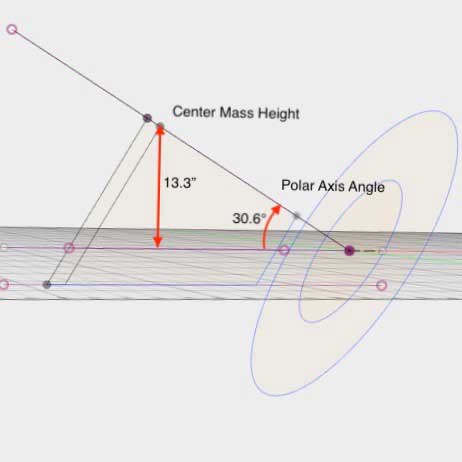
Figure 1
Sketch depicting polar axis angle and center mass height
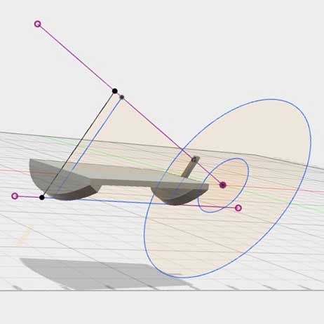
Figure 2
Sketch depicting top platform piece
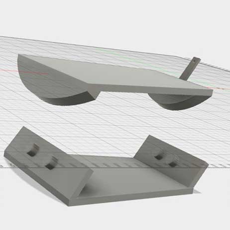
Figure 3
Sketch depicting top equatorial platform piece above the bottom base
Build Process
Measure center of mass of skywatcher mount
Use center of mass and latitude angle to design DOB platform using Autodesk Fusion360 software. See Figure 1 above.
Buy project materials
Make cuts on wood purchased for project
Assemble cut parts
Wire motor driver circuit and program controls
Design and 3D print motor control box.
Take 1st pictures of object while tracking. (Still need to complete this!)
Calculations Used
Height of Center Mass
H_tube is center mass height of my telescope, M_tube is mass of my telescope, H_mount is the center mass height of telescope mount, M_mount is the mass of telescope mount. HCM = (H_tube * M_tube + H_mount * M_mount)/(M_tube + M_mount) = weighted center mass height of the Dobsonian telescope and mount as a unit. Note: this is the original mount the telescope comes with to adjust azimuth and altitude angles manually.
To Determine H_Mount:
1. Pick up mount by side handle to determine pivot point. Then measure distance from pivot to base of mount.
HCM= 13.3" or 338.362mm
To Determine how to Couple 3d Printed Gears:
2. Pitch diameter big gear = 1115.20 mm, r = 557.6 mm
3. Little gear = 65.6 mm, r = 32.8 mm
4. 590.4 mm center to center, is distance used to couple the large spur gear to small spur gear. Note the small spur gear is part of the planetary gear as one unit.
To Determine the Input Rate of Planetary Gear to Spur Gear Design:
5. gear ratio = big gear : small gear = 557.6 mm/32.8 mm = 17
6. Vout = 1 rotation/day = (gear ratio)(1 rotation/1440 minutes), using 1 day = 1440 minutes. Therefore, Vout = 17 rotations/1440 minutes = 0.0118 rotation/minute. This output velocity of the spur gear which matches earth's rotational velocity. Notice how slow this is.
7. Vin = (gear ratio/1440)(Rotations/Minute)(60) = 0.0118 rotation/minute x 60 = 0.7 rotation/minute. This is speed of the input planetary gear. The factor of 60 comes from the step down such that 60 turns on the input planetary gear equals 1 turn on the output spur gear.
8. 6.7V at 0.4A = 2.68W = torque x speed This equation shows a rough equality of power supplied to torque used at fixed speed.
9. Speed = 0.7 rotation/minute = 2.361111 steps/second, using Nema 17 stepper motor specifies 200 steps/rotation and 60 seconds/minute.
10. 1/speed = 0.4235294118 seconds/step. Inverting the speed gives the useful quantity. This parameter is used in the micro controller code as a wait function to control the motor. So about every 0.42 seconds, the motor takes a step to match earth's rotation.
Project Pictures
Click each image to see a larger photo.
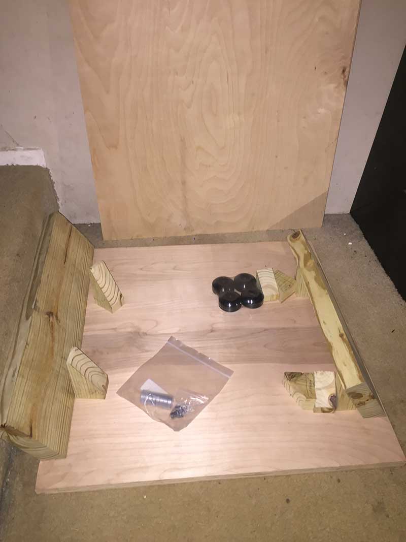
Photo 1
Rough cuts, skateboard wheels, and bearings used for initial assembling of base platform are assembled.
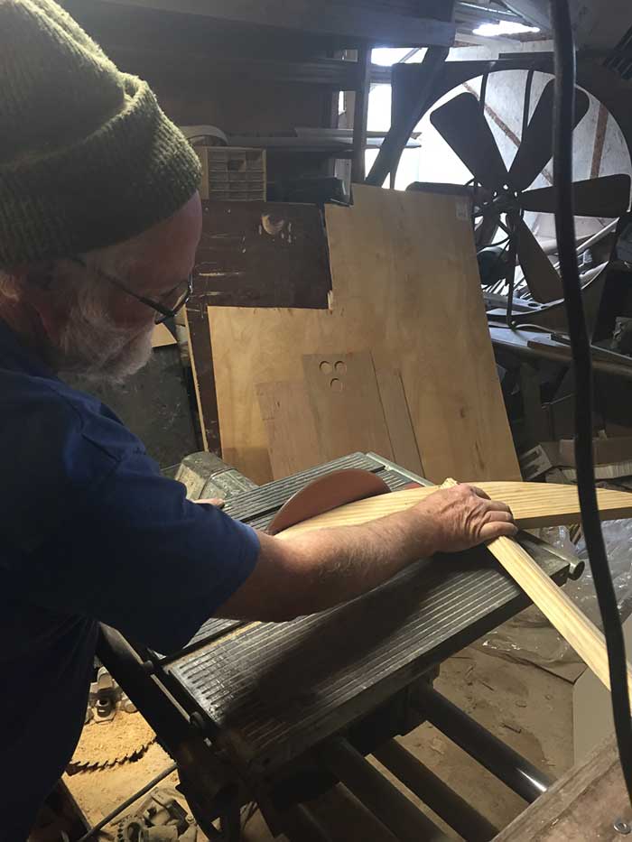
Photo 2
BVAC President, Tim Cowden, helped make the curved cuts for the top part of equatorial platform. We used Tim's ShopSmith with a wheel grinder attachment to make the curved cuts by moving a pivot arm about a determined radius.
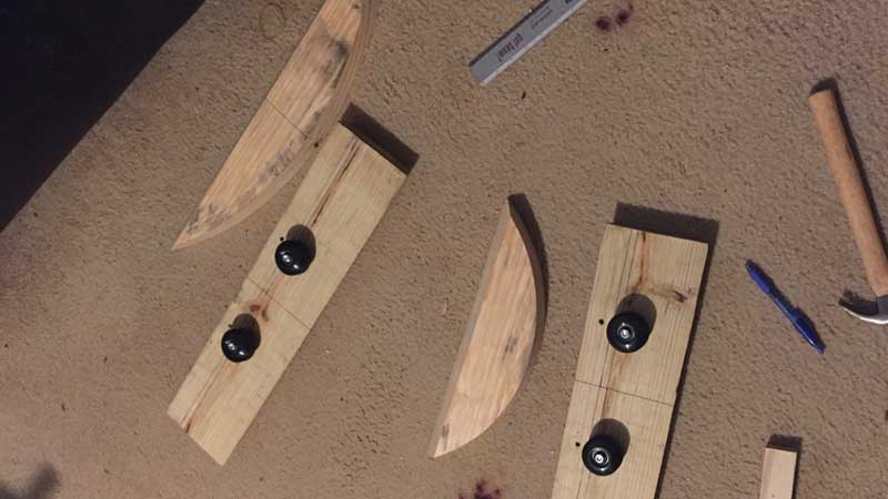
Photo 3
Finished cuts and skateboard wheels are attached to support boards.
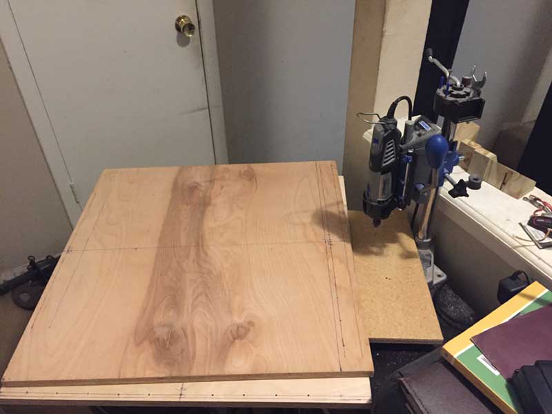
Photo 4
The top platform is set up for drilling holes using a Dremel tool. Pre-drilling the holes helped keep the round cuts from moving when attaching to square piece by drilling screws. I found that without pre-drilled holes, the round cuts would lose alignment on the square base.
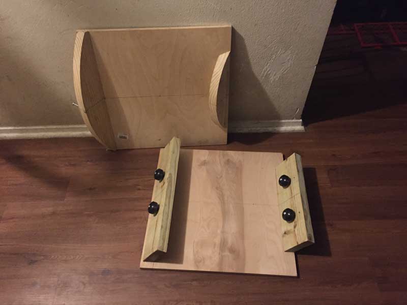
Photo 5
The round cuts to the square top and bottom base are assembled. Leaning against the wall is the top part, and the bottom base has skateboard wheels attached to support boards.

Photo 6
The platform is fully assembled with linear motion to angular motion drive system. This system introduced more complexity I didn't want to deal with, so I decided to scrap the drive system.
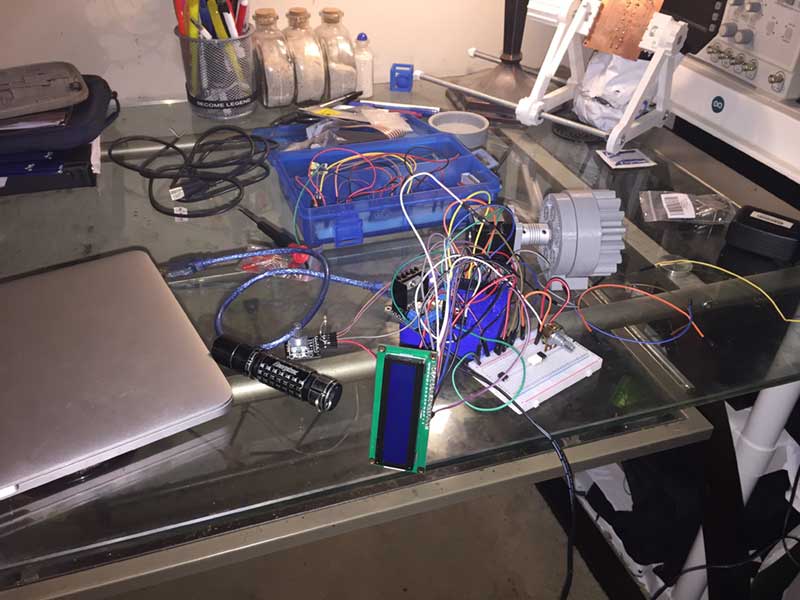
Photo 7
The control system wiring for the equatorial platform is complete. Notice the grey colored gear attached to the motor. This is the designed and 3D printed part used for direct system drive. The motor is coupled to the input(60 turns) planetary gear and the output(1 turn) has the spur gear attached.

Photo 8
The direct motor drive control system and 3D printed housing with LCD display are ready. Notice the grey slide motor mount that allows the motor to pull back to decouple the small spur gear to the large one to reset the top platform once it has traveled its limit.
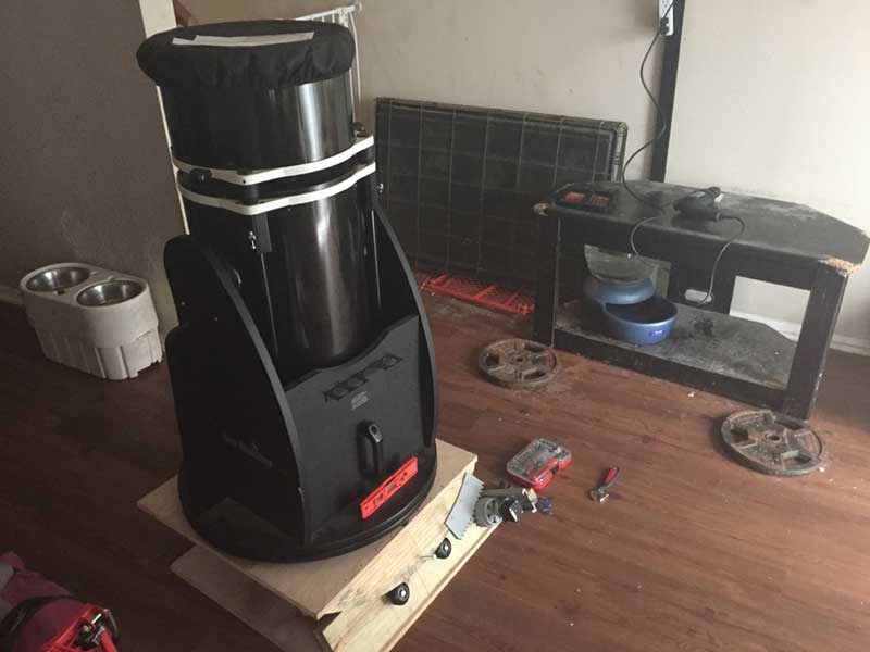
Photo 9
My Dobsonian telescope with mount on top of the built equatorial platform is finished.
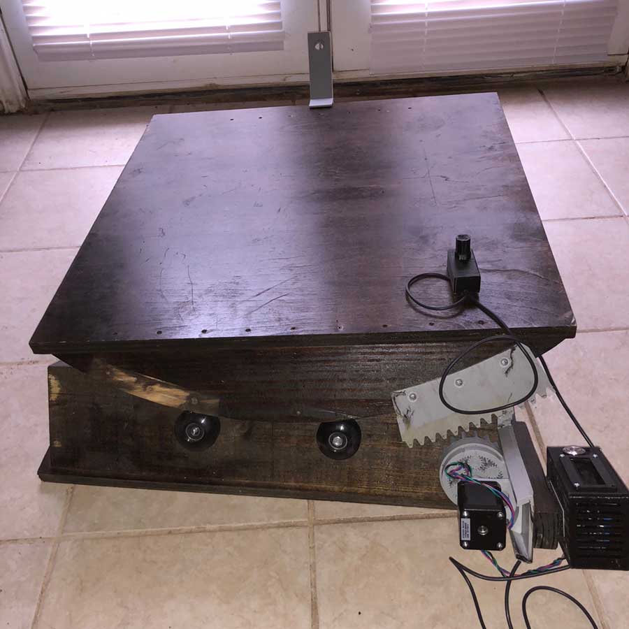
Photo 10
The Finished Project - Click to see larger image.
Conclusion
You will notice that the paint job on the front cover image looks like paint is missing on the front left side of equatorial platform. That is because I made a mistake when testing this mount. I originally had the drive system mounted on the front left side rotate clockwise about the polar axis when aligned toward it. This matches earth's rotation in the same direction. In this configuration, I noticed the image would move out of FOV twice as fast. So I corrected this mistake and mounted it on the right side of equatorial platform and haven't painted over the old motor mount spot. I could have left the motor in the old mount spot and reversed the rotation, but it would have done more work against gravity. From Calculations Used, in Section 8, more torque at a fixed speed equals more power used. Trying to minimize power needed for this project, I chose to move the motor mount so that is turns counter clockwise about the polar axis when facing toward north star. Also, the motor mount position allows for gravity to help with work done during tracking. The drive system rotation is opposite of earth's rotation at the same speed of 1 rotation per day, which nullifies object movement on the telescope eyepiece. I verified this once on the moon and it stayed put for a good 30 minutes. Unfortunately, I have yet to try and capture an image of DSO using this equatorial platform built because I have not found time where weather and scheduling permits.
This project first started January 2017. I first drew up the equatorial platform parts using CAD program. These parts depend on the polar axis angle and center mass of telescope with the mount used. After completing the drawing, I now had the dimensions needed for the cuts. So I eventually purchased all the material for the project by the end of 2017. A coworker helped with some easy cuts, and BVAC President Tim Cowden helped with the curved cuts. I had to change the drive system to make programming easier, and I had to correct the direction the mount rotated when aligned with the North Star. This amateur astronomy project has proven to be a learning experience that I enjoyed in my free time, and I will continue to work to get this system to produce a picture with my Canon camera - hopefully someday soon!
Equatorial Platform Bill of Materials
The following is the bill of materials for the equatorial platform report.
| Item Number | Part Number | Description | Quantity | Unit Cost | Total |
|---|---|---|---|---|---|
| 1 | B00J9VPSF8 | 52mm Wheels w/Bearings and Spacers | 1 | 12.60 | 12.60 |
| 2 | B00VK1GF4G | Arduino Pro Mini 5V | 1 | 12.25 | 12.25 |
| 3 | B01E1XKLIC | 1.75 Grey PLA 3D Printer Filament - 1 kg Spool | 1 | 21.99 | 21.99 |
| 4 | 90433 | L298N H-bridge Motor Driver Board | 1 | 7.01 | 7.01 |
| 5 | 17HS24-0644S | High Torque Low Current Nema 17 Stepper Motor 85 oz.in/60Mcm 0.64A | 1 | 25.00 | 25.00 |
| 6 | N/A | 3/4-in Birch Plywood, 2 ft x 4 ft | 1 | 24.98 | 24.98 |
| 7 | N/A | 2in x 12in x 12ft Lumber | 1 | 17.11 | 17.11 |
| 8 | 63315 | Hillman Standard (SAE) Hex Bolt | 4 | 0.22 | 0.88 |
| 9 | 63301 | Hillman 1 Count 1/4in Standard (SAE) Hex Nut | 4 | 0.06 | 0.24 |
| 10 | B07FP6TY9P | Mount with Leveler | 1 | 22.99 | 22.99 |
| 11 | B005YSXPQE | HD44780 16x2 Red Text LCD | 1 | 9.69 | 9.69 |
| 12 | B06ZZ17SVL | Pushbutton Switch ON/OFF Silver Stainless with 12V Red LED | 1 | 9.55 | 9.55 |
| 13 | B06Y2JHGGV | Multicolored Wire Kit | 1 | 11.99 | 11.99 |
| 14 | PEC16-4220F-S0024 | Rotary Encoder w/Pushbutton Switch | 1 | 1.59 | 1.59 |
| 15 | 222504444 | MINWAX Wood Finish, Stains and Seals | 1 | 4.99 | 4.99 |
| 16 | 33250000 | MINWAX Spar Urethane, Protection from Sunlight & Rain | 1 | 9.99 | 9.99 |
| TOTAL | $192.85 |
